Part 1: Configuring & Understanding the Settings in CATIA with Shortcut Keys!!
The importance of configuring and understanding the settings in CATIA lies in their direct impact on your user experience, efficiency, and the overall performance of your design work. Here are several reasons why CATIA settings are crucial. Let’s get some problems and with solutions that highlights the shortcut keys in CATIA. Let’s Begin!
2024-03-21

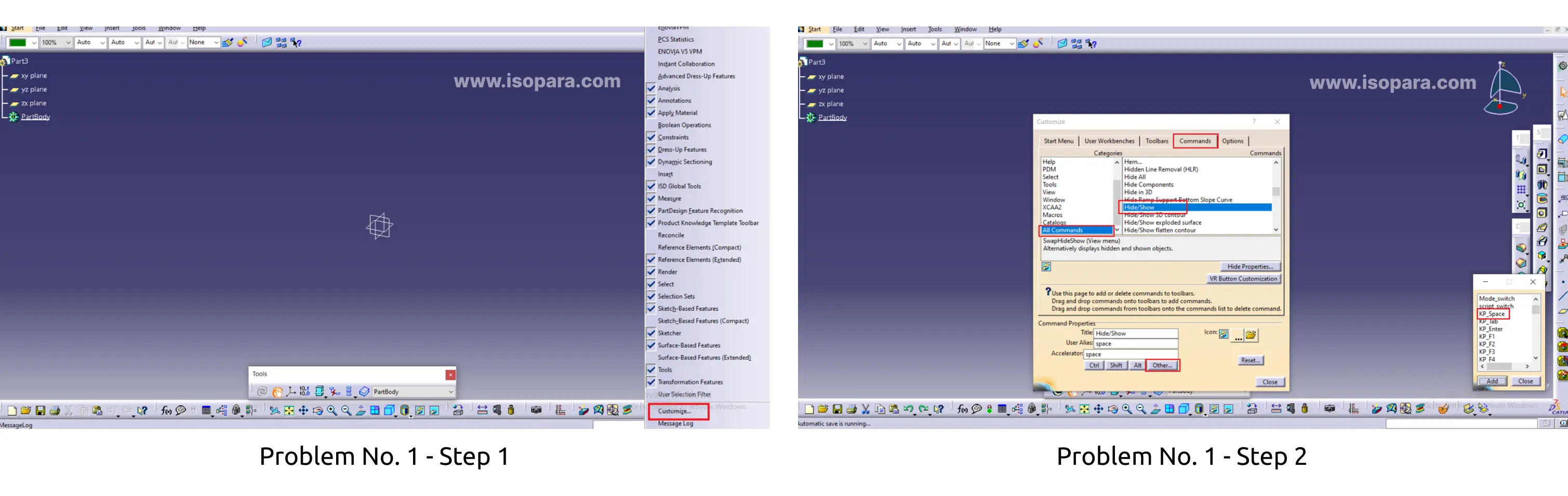
Problem No. 1: If you want to add Hide/Show shortcut key.
Solution: “Go to Tools > Customize... in the menu bar.”
The shortcut keys for hiding and showing are highly convenient, especially when used repeatedly. Opting for the space key proves to be an excellent choice, ensuring easy accessibility.
Problem No. 2: How to change axis system size.
Solution: Customizing Keyboard Shortcuts: Go to Tools > Options...>Part Infrastructure>Display in the menu bar.
The size of the axis system in CAD work can sometimes be challenging, being either too large or too small. It would be beneficial to have the flexibility to adjust the axis size according to our specific needs.
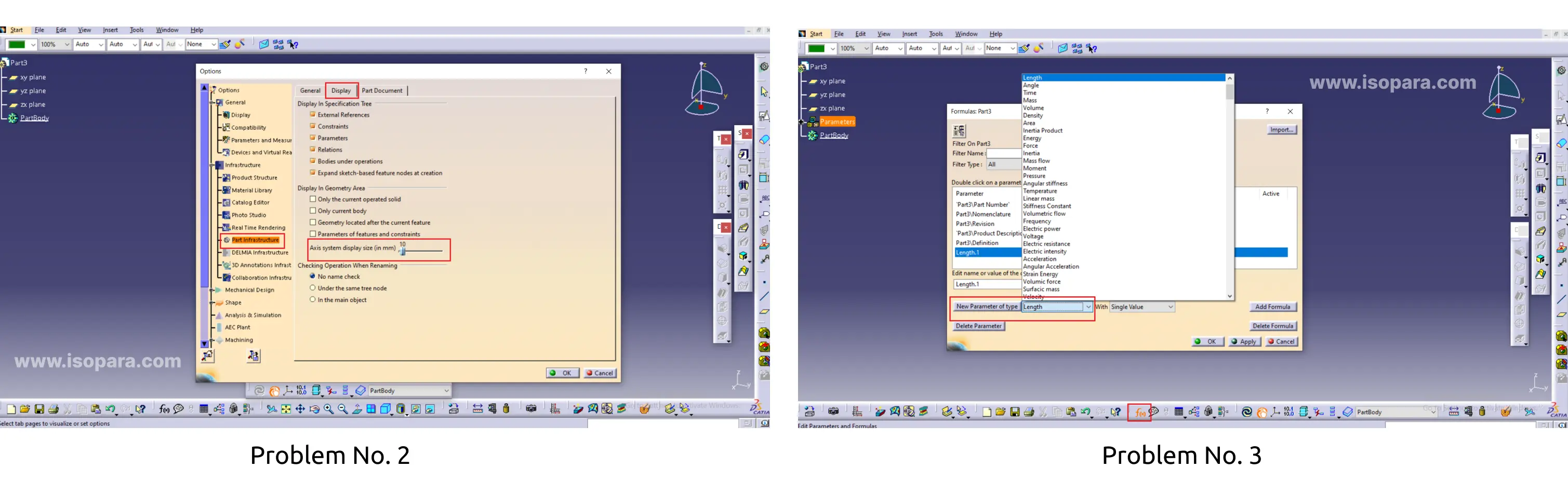
Problem No. 3: How to add Parameter
Solution:
1) Parameter Types:
Real: Represents numerical values (e.g., dimensions, distances).
String: Represents text values.
Integer: Represents whole numbers.
Boolean: Represents true or false values.
2) Creating Parameters: Parameters can be created in the "Insert" menu under "Object" and then selecting "Parameter." You can define the name, type, and initial value of the parameter.
3) Linking Parameters: Parameters can be linked to various elements in the model, such as dimensions, features, or constraints. Right-click on a dimension or feature and choose "Link to a Parameter" to associate it with an existing parameter.
4) Formulas: Formulas can be created to express relationships between parameters. For example, you can set one parameter to be equal to the sum or difference of other parameters.
5) Assembly Parameters: In the Assembly workbench, parameters can be applied to control the position and behavior of components within an assembly. Rules and relationships between parameters can be defined to capture the assembly's dynamic behavior
Problem No. 4: The parameter has been configured, but it does not display option in Main tree.
Solution: Go to Tools > Options...>Part Infrastructure >Display in the menu bar.
In CATIA, a parameter is a variable that holds a specific value and can be used to define various aspects of a model or design. When referring to the "length parameter" in CATIA, it typically means a parameter that represents the length of a particular feature or component within the CAD (Computer-Aided Design) software. For example, if you have a line or a solid object in your CATIA model, you might want to define its length using a parameter. This allows you to easily modify the length later on without having to manually change every instance where that length value is used
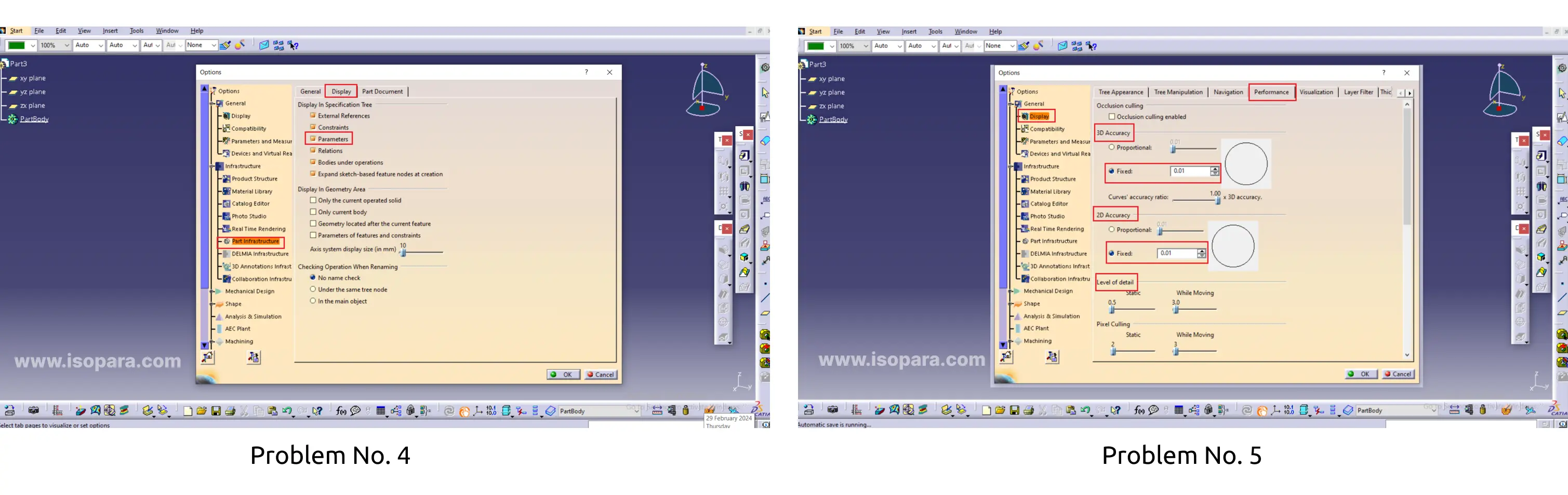
Problem No. 5: How to improve graphics quality in catia V5.
Solution: Go to Tools > Options...>Display > Performance in the menu bar.
In CATIA V5, improving graphics quality can enhance the visual representation of your 3D models. Here are some tips to help you optimize and enhance graphics quality in CATIA V5. Sometimes graphics quality may be insufficient, prompting us to enhance it using the following steps.
Problem No. 6: Change Background color.
Solution: Customizing Keyboard Shortcuts: Go to Tools > Options...>Display > Visualization in the menu bar.
In CATIA V5, you can customize the background color to suit your preferences. Here's how you can change the background color:
- Open CATIA V5 and open a part or assembly document.
- Go to the "View" menu in the menu bar.
- Select "Background" from the drop-down menu.
- A sub-menu will appear with color options. Choose the desired background color from the available options. If you want to set a custom color, select "More Colors" from the sub-menu. This will open a color picker dialog where you can choose a specific color.
- Once you've selected the background color, it should be applied to the active document.
Keep in mind that the steps might slightly vary depending on the version of CATIA V5 you are using. This process ensures that the background color is adjusted to your preference for a more personalized working environment.

Problem No. 7: Cache management to optimizing performance
Solution: Go to Tools > Options...>Display > Visualization in the menu bar.
In CATIA V5, cache settings are essential for optimizing performance and responsiveness. However, there isn't a specific "cache activation" command. Instead, CATIA V5 manages caching automatically. The cache settings control the use of memory and disk space to store frequently accessed data, improving loading times and overall performance.
Here's how you can access and manage cache settings in CATIA V5:
- Open CATIA V5 and go to the "Tools" menu in the menu bar.
- Select "Options" from the drop-down menu.
- In the Options dialog box, navigate to the "General" category.
Under the "General" category, you will find settings related to cache management.
- Cache Options: Adjust settings related to disk cache and memory allocation to optimize performance.
- Memory Management: CATIA V5 allows you to allocate a specific amount of memory for cache purposes. Adjust the memory settings based on your system's capabilities.
- Temporary Directory: Define the location on your disk where temporary files, including cache data, are stored.
Once you have adjusted the cache settings, click "OK" to apply the changes.
By configuring cache settings appropriately, you can enhance the loading times of CATIA V5 and improve overall performance. Keep in mind that managing cache settings may require some experimentation to find the optimal configuration based on your hardware and the complexity of your models.
Problem No. 8: Add shortcut to part Design, Generative Shape Design
Solution: Go to Tools > Customize... in the menu bar.
In CATIA V5 Part Design workbench, there are several keyboard shortcuts that can enhance your efficiency.
- CATIA V5 Part Design Workbench: CATIA (Computer-Aided Three-Dimensional Interactive Application) is a software suite used for product design and manufacturing. The "Part Design" workbench is a specific module within CATIA focused on creating and modifying 3D solid models.
- Keyboard Shortcuts: Keyboard shortcuts are combinations of keys that, when pressed together, trigger specific commands or actions. In CATIA V5 Part Design, these shortcuts are designed to streamline common tasks and improve the overall user experience.
- Enhance Your Efficiency: The statement suggests that using keyboard shortcuts in the Part Design workbench can enhance efficiency. By relying on these shortcuts, users can perform tasks more quickly than navigating through menus with a mouse, saving time and improving workflow.
- Several Shortcuts: CATIA V5 Part Design provides various keyboard shortcuts to cater to different functions within the software. These shortcuts cover actions such as sketching, creating features like pads and chamfers, general commands like undo and redo, and navigation within the 3D workspace.
- Customization: Users often have the flexibility to customize or modify keyboard shortcuts based on their preferences. This allows individuals to tailor the shortcuts to match their workflow and habits.
- Efficient Navigation and Modeling: Whether rotating the view, creating sketches, applying features, or measuring dimensions, keyboard shortcuts offer a quick and direct way to execute commands. This contributes to a smoother and more efficient experience in designing 3D parts.

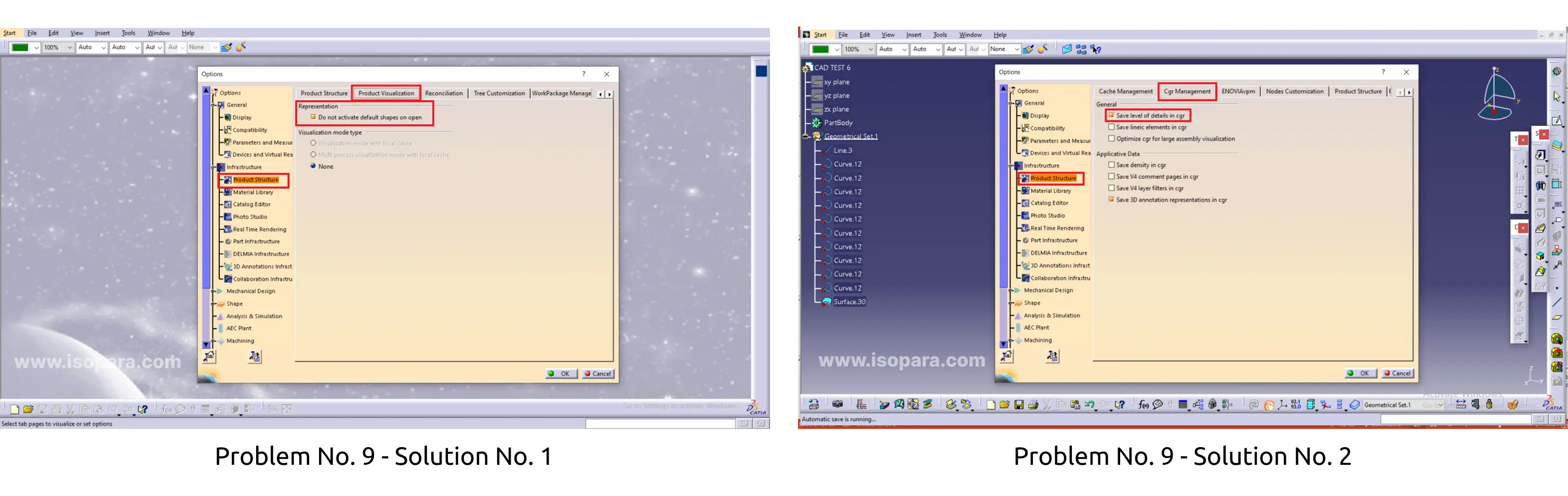
Problem No. 9: Add fast opening of assembly
Solution No. 1: Go to Tools > Options...>Infrastructure > Product Structure > Product visualization in the menu bar.
Working with large or heavy assembly files in CATIA may require some adjustments to optimize performance. Here are some settings and tips to consider.
Visualization Modes: Use simplified visualization modes (e.g., Shading with Edges) instead of more detailed modes to reduce the graphical load on your system
Solution No. 2: Go to Tools > Options...>Infrastructure > Product Structure > Cgr Management in the menu bar.
Displaying CGR Models: When CGR mode is active, CATIA displays the CGR representation of the model. This can be a simplified graphical representation, making it easier to work with extensive assemblies without experiencing lag or delays
Author

Aniket Bhilare ( Design Engineer)
Total 1 Blogs viewI am a design engineer.Isopara has proven invaluable for creating precise and efficient designs in CATIA V5 for plastic products. Its intuitive features help me generate accurate part geometries and streamline the design process. Isopara's integration with CATIA V5 enhances my productivity, enabling me to iterate quickly and produce high-quality designs with ease. Overall, Isopara has played a key role in optimizing my design workflow and achieving success in plastic product design projects.
Author’s journey so far:
ISOPARA is best for training in Automotive Design.
Course done and recommended by Author:
Share This Page


Other Trending Videos
- 3-Steps || Choose the Right CAD Software with the Right Domain
- Roadmap || Become an Automotive Design Engineer in BIW Domain.
- Roadmap || Become an Automotive Design Engineer in Plastic Domain
- Not Getting Interview CALLS? || Career Guidance
- Mechanical Design Jobs || Domain Skill
- Why CAD and its Importance? || By Experts
- Difference || CAD Engineer Vs Design Engineer
- Best CAD Software to Learn & Build a Career || By Experts
- Best CAD Software to Learn || Most Demanded by Industries
- How to Become a Design Engineer? || By Expert.